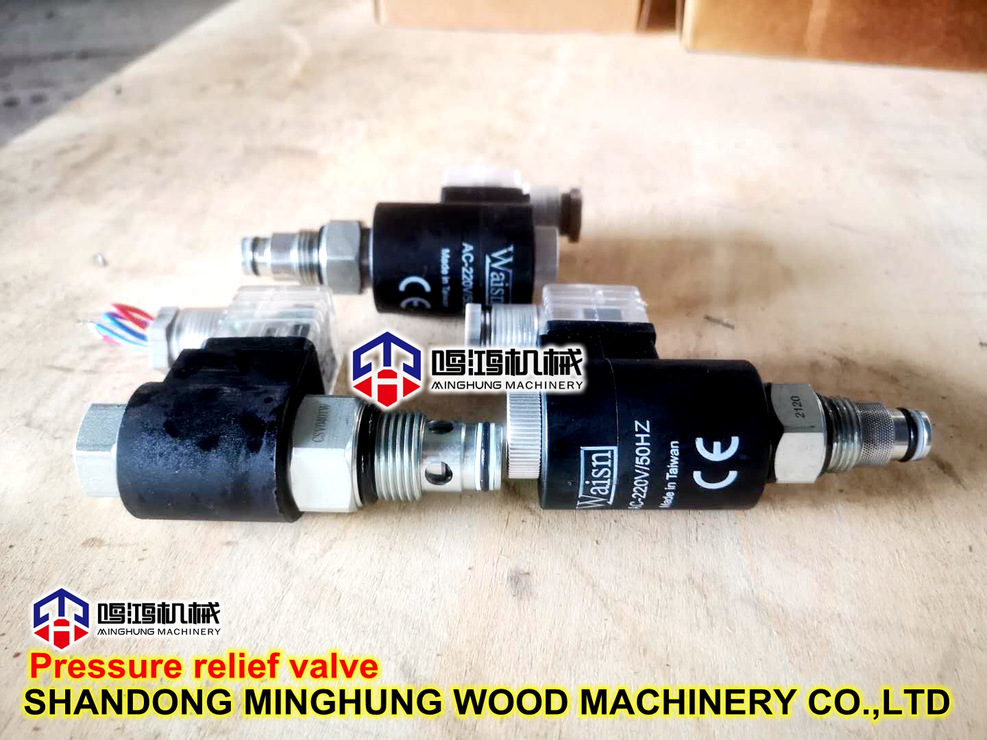
hydraulic accessories solenoids Valve for press machine hydraulic station
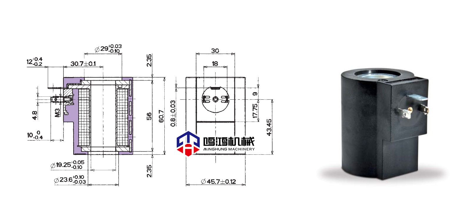
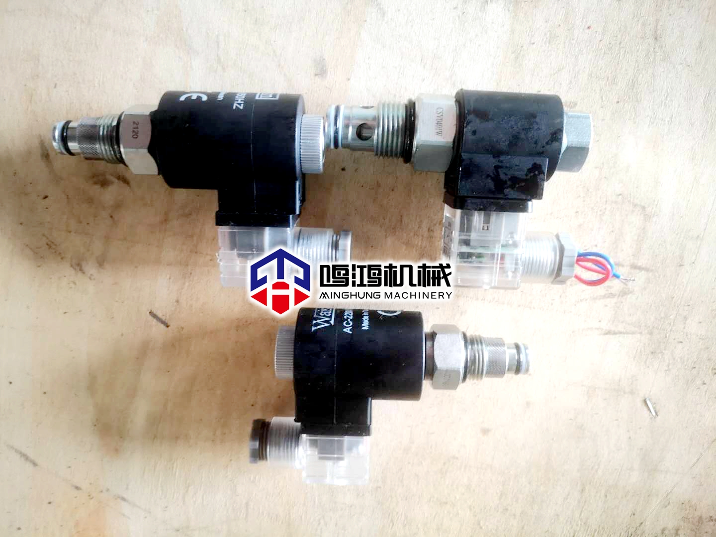
MINGHUNG hydraulic control pressure relief valve structure design and working principle
In the water pump water pipeline system, when the pump is suddenly stopped, the pump outlet check valve is quickly closed, causing the circulation flow rate in the valve outlet pipeline to suddenly drop, and the return shock pressure is generated. The sudden change in the speed will cause the shock pressure wave transmission and the transmission speed. Very high, the pressure at the outlet section of the valve can be increased to several times the rated pressure. This is the water hammer phenomenon in the pipeline, which can cause the valve or pipeline to rupture and cause an accident. In order to avoid such accidents, people currently use valves with delayed closing characteristics, such as two-stage control closing butterfly valves, hydraulic control valves with daughter and mother valve plates, slow closing check valves, etc., so that the valve is delayed to close, and some water passes through. The pump and rotor components return to achieve the purpose of pressure relief to eliminate water hammer pressure. However, due to the long pressure relief time, the backflow water impacts the impeller of the pump for a long time, which accelerates the reversal speed of the pump rotor components, and the long time will damage the pump rotor
Parts and motor rotor parts associated with it.
In order to solve the above problems, it is necessary to design an automatic pressure relief valve installed on the MINGHUNG DYDRAULIC MACHINE pipeline, which can lead the return flow to the pump inlet within the pressure relief time, that is, the pressure relief return flow will no longer pass through the pump rotor components to complete the relief. The pressure energy is automatically closed, which completely solves the problem of the reverse pressure of the pressure relief return impact pump, and achieves the purpose of effectively eliminating water hammer.
1 Structural design
The valve consists of a valve body, a hydraulic chamber, a hydraulic pipe a and a hydraulic pipe b. The valve body is a four-way pipe with a hydraulic drive rod, a lower valve plate, and an upper valve plate inside. The two ends of the hydraulic drive rod are provided with threads. The lower part of the valve body is connected with the bottom cover by connecting screws. There is a water inlet and outlet on the upper and lower sides of the valve body to connect with the pipeline. The middle of the valve body is close to the upper water inlet and outlet, and the upper valve plate is connected with the hydraulic transmission rod by welding. The plate is connected with the hydraulic transmission rod through a nut and a thread at one end of the hydraulic transmission rod, and the upper part of the valve body is connected with the hydraulic cavity through a flange. The hydraulic chamber is composed of a hydraulic chamber seat, a hydraulic chamber cover, a hydraulic chamber and a piston. It is integrated with the valve body through a screw and nut. The hydraulic chamber seat is equipped with a hydraulic chamber seat cover, the piston is in the hydraulic chamber, and the hydraulic transmission rod passes hydraulic pressure. The cavity seat cover is connected with the piston by a nut and a thread at one end of the hydraulic transmission rod. The piston divides the hydraulic chamber into an upper chamber and a lower chamber. There is an "O"-shaped sealing ring on the piston. The "O"-shaped sealing ring on the piston is tightly sealed with the inner wall of the hydraulic chamber to completely isolate the upper and lower chambers of the hydraulic chamber. The hydraulic chamber cover is provided with a flow hole, and the hydraulic pipe a is connected with the upper cavity of the hydraulic chamber through the flow hole. The hydraulic chamber seat is provided with a through hole, and the hydraulic pipe b is connected with the lower cavity of the hydraulic cavity through the through hole and connected with the lower cavity of the hydraulic cavity.
Install "O"-shaped sealing rings on the upper valve plate, lower valve plate, and hydraulic chamber seat cover, install the sealing gasket on the stop matching surface between the hydraulic chamber cover and the hydraulic chamber, and install the sealing gasket on the hydraulic chamber and the hydraulic chamber seat A sealing gasket is installed on the stop matching surface between the hydraulic chamber seat and the valve body, and the sealing gasket is installed between the valve body and the bottom cover and the stop matching surface. Install the filter and the regulating valve micro check valve on the hydraulic pipe a, and install the filter and the regulating valve on the hydraulic pipe b. A through hole is opened on the hydraulic chamber cover, and the hydraulic pressure is connected through the through hole.
The pipe c is equipped with a micro check valve and a bleed screw plug is installed above the hydraulic chamber cover. A bleed screw plug is installed on the hydraulic chamber cover, which can be used to release the gas in the upper chamber of the hydraulic chamber.
The hydraulic chamber is composed of a hydraulic chamber seat, a hydraulic chamber cover, a hydraulic chamber and a diaphragm upper plate, a diaphragm, and a diaphragm gland. The diaphragm upper plate, diaphragm, and diaphragm gland are in the hydraulic cavity, and the diaphragm upper plate On the diaphragm, the diaphragm is covered under the diaphragm, the hydraulic transmission rod passes through the hydraulic cavity seat cover, and the screw at one end of the hydraulic transmission rod is integrated with the diaphragm cover, the diaphragm, and the diaphragm upper plate. The cavity cover, the diaphragm and the hydraulic cavity are connected by screws and nuts. The diaphragm divides the hydraulic cavity into upper and lower cavities and completely isolates the upper and lower cavities.
2 Working principle and function
The MINGHUNG hydraulic control pressure relief valve with the above structure is used in the delivery fluid pipeline system. It is installed on the bypass pressure relief pipeline on the outlet side of the pump outlet check valve to achieve the following functions and use effects. When the pump is in the starting state, the pressure in the lower chamber of the hydraulic chamber connected with the hydraulic pipe is higher than the pressure in the upper chamber of the hydraulic chamber connected with the hydraulic pipe. Under the action of the pressure difference, the piston moves upward and drives the lower valve plate through the hydraulic transmission rod. Move upward, at this time, liquid enters the lower water inlet and outlet, and flows out from the upper water inlet and outlet through the valve body. When the piston moves upwards and drives the lower valve plate upward through the hydraulic transmission rod until the lower valve plate contacts the sealing seat in the valve body, the "O"-shaped sealing ring 5 on the lower valve plate is compressed and plays a sealing role. There is no liquid flow in the upper water inlet and outlet and the lower water inlet and outlet. At this time, the pump and piping system are in normal working condition. The hydraulic pipe connected to the hydraulic cavity cover can speed up the fluid flow in the hydraulic cavity, so that the process can be carried out quickly.
When there is a sudden power failure, the check valve is automatically closed. At this time, the pressure in the upper chamber of the hydraulic chamber is greater than the pressure in the lower chamber of the hydraulic chamber. The piston moves downward under the action of the pressure difference and drives the lower valve plate to move downward, forming an "O" shape. The sealing ring loses its sealing effect, and liquid flows into the upper water inlet and outlet and is discharged from the lower water inlet and outlet through the valve body. At the same time, the upper valve plate is also moved downwards synchronously under the drive of the hydraulic transmission rod until it contacts the sealing seat in the valve body. The O"-shaped sealing ring is compressed to play a sealing role. At this time, the liquid flow in the upper water inlet and outlet is stopped, and the hydraulic effect is eliminated. The time from when the lower valve plate and the upper valve plate move downwards at the same time, the "O"-shaped sealing ring loses its sealing effect to the time when the "O"-shaped sealing ring plays a sealing role is the pressure relief time.
The gasket is used to ensure that the liquid in the hydraulic chamber does not leak, and the gasket is used to ensure that the liquid in the valve body does not leak. The "O" seal ring on the hydraulic chamber seat cover is used to isolate the liquid in the hydraulic chamber and the valve body. In order to adjust the pressure relief time, a regulating valve is installed on the hydraulic pipe, and the pressure relief time can be adjusted by controlling the inflow and outflow speed of the liquid in the upper and lower chambers of the hydraulic cavity through the regulating valve. A filter is installed on the hydraulic pipe to filter impurities in the liquid to ensure cleanliness in the hydraulic cavity. A micro check valve is installed on the hydraulic pipe, which can be used to throttle the water flow into the upper cavity of the hydraulic chamber. The valve action is flexible and the closing time is adjustable (the fastest 15s, the slowest 348s). For complex pipe network systems, the effect of eliminating water hammer is good, and it completely solves the problem of long slow closing time of the two-stage closing check valve and reverse water impact on the pump. The problem of transfer.
3 Application
Three types of pressure relief valves with a diameter of 80mm, 150mm, and 300mm have been designed and manufactured, with a nominal pressure of 1.6MPa, which are used in tap water, metallurgical cooling circulating water, and petrochemical cooling circulating water pipeline systems. After nearly 1 year of operation, the valve is flexible. The closing time is adjustable. For complex pipe network systems, the effect of eliminating water hammer is good, and the problems of long slow closing time of the two-stage closing check valve and reverse water impact and reverse are completely solved. It shows that the valve structure and performance design method is feasible, and the parameter selection is accurate.
The MINGHUNG hydraulic control pressure relief valve is installed on the bypass pipeline on the outlet side of the check valve in the main pipeline. It is used in conjunction with the check valve. The pressure liquid in the pipeline is used to achieve drive and automatic control, which completely solves the traditional two-stage shut-off valve. Eliminate the problem of reverse rotation of the pump rotor when the water hammer pressure is discharged. Because it has the function of adjustable closing time, it is suitable for various complex pipelines to eliminate water hammer pressure. It is a new type of pressure relief valve with popularization and application value.