Plywood sander technical manual
plywood calibrating machine technical manual
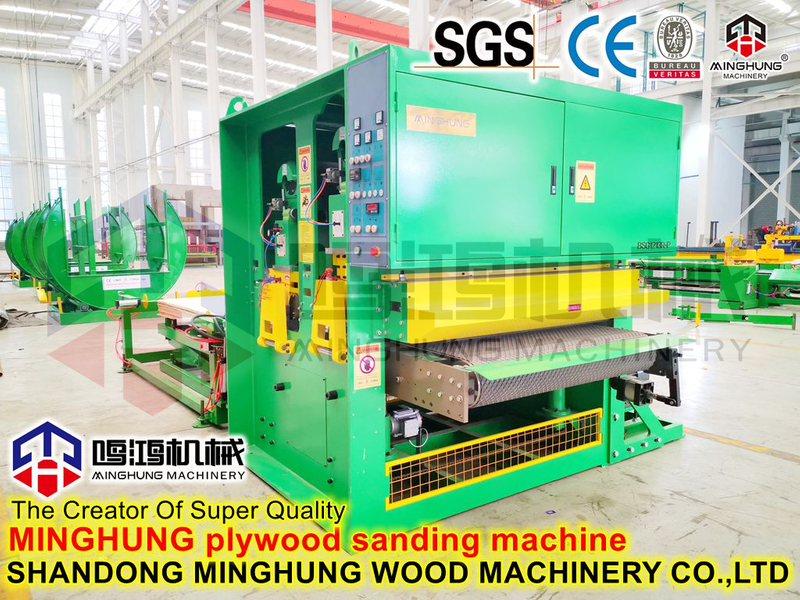
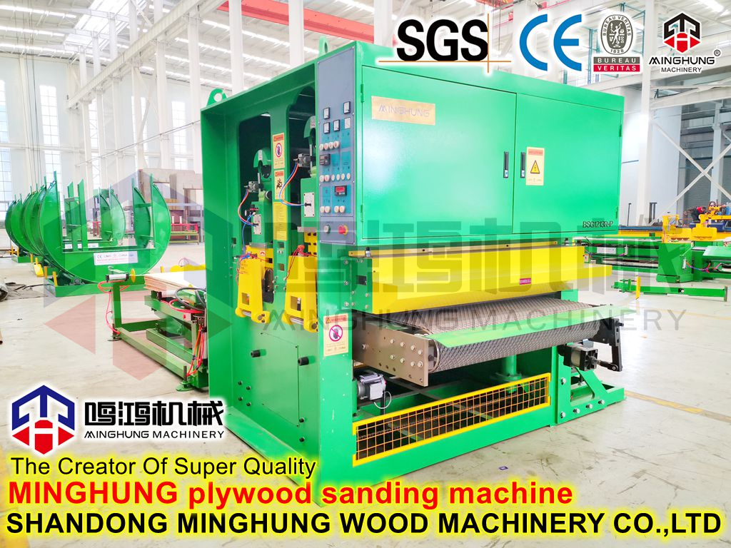
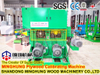
1. The plywood sander is mainly used for fine sanding and re-polishing on the surface of plywood, various multi-layer boards, blockboard, particle board, medium density fiberboard and other boards.
The main performance characteristics of the machine tool are as follows:
(1). The body adopts the overall box-shaped welding structure, which has sufficient rigidity and the service life of the machine tool is high.
(2). The diameter of the sanding roller is large, which increases the service life of the sanding belt, and it works smoothly through precise dynamic balance.
(3). The sanding roller adopts a soft rubber roller to ensure good contact between the abrasive belt and the plate without sanding through the surface material of the plate; the sand pad adopts an airbag sand pad to ensure an excellent polishing effect on the surface of the plate.
(4). The feeding adopts the roller feeding stepless frequency conversion speed change, the feeding speed can be as high as 78m/min, and the production efficiency is high.
MINGHUNG MACHINERY More about plywood sanding machine contact us:
whatsapp: +8618769900191 +8615589105786 +8615805493072
website: www.plywoodmachineline.com
email: minghungmachinery@gmail.com


2. The main parameters of the machine tool:
Processing width:50-1300mm
Processing thickness:3-60mm
Processing length:≥1000mm
Belt motor:45+37+22kw
Belt speed:18.5m/min
Belt size:1300x2620mm
Automatic feeding system whine motor:7.5kw
Lifting system motor:1.1kw
Brush roller motor:0.75kw
working pressure:0.4-0.7MPa
Compressed air consumption:1m3/h
Vacuum speed:20-30m/s
Vacuum air volume:18000 m3/h
3. Basic composition of plywood sander
The machine tool mainly consists of the following parts:
(1). Machine body: responsible for the connection of sanding head, feeding device, lifting device and other machine tool components.
(2). Lifting hand wheel: used for fine-tuning the lifting of the feeding table.
(3). Various power mechanisms: provide the power required by the sanding head, feeding device, lifting device, and brushing device.
(4). Lifting device: The cycloidal pin wheel reducer drives the lead screw in the worm gear reducer to lift up and down through the chain drive, thus completing the lifting of the feeding table supported on the top of the lead screw.
(5). The conveyor bed is composed of driving rollers, driven rollers, support rollers and bed body. The 4Kw reducer adopts frequency conversion speed regulation, and its feeding speed is 6~35m/min.
(6). Upper feeding roller: there are five in total, all of which are driven feeding rollers, which mainly play the role of pressing material. Their position and pressing force directly affect the sanding quality of the workpiece, and must be carefully adjusted.
(7). Brushing roller: used to remove the dust bonded on the surface of the workpiece.
(8). Electrical control box: the electrical components of the machine are assembled in it. Please refer to the attached drawing for the electrical schematic diagram.
(9). Sand frame: The sanding element is a sanding roller, which uses a soft rubber roller, and the abrasive belt has a finer grain size, which is used for fine sanding of the workpiece.
(10) Polishing frame: The polishing element is an airbag pad, and the abrasive belt has a finer grain size, which is used for fine polishing of the workpiece.
(11). Operation panel: used for machine tool operation control and status display.
(12). Center bracket: it supports and locks the beam function of each sanding head.


4. Installation of the machine tool
4.1 Leveling of the machine tool
Use the four lifting rings on the top when lifting the machine tool. In order to keep the machine tool balanced, use a long enough wire rope (or chain) and ensure that the wire rope (or chain) is firm and reliable.
When the ground is hard, the machine tool can be placed on six 150×150×20mm pad irons, and then a level ruler is placed on the feeding roller, and a level is placed on the flat ruler, and then the bolts on the upper part of the shim iron are adjusted. Make the readings of the machine tool's level instrument in both vertical and horizontal directions not exceed 1000: 0.10mm.
When the ground is soft and cannot bear the load of the machine tool, it is necessary to pour the cement foundation, lay the foundation and make reserved holes, put expansion cement and anchor screws in the reserved holes, install the machine tool, and then adjust the machine tool in both vertical and horizontal directions To a proper horizontal position, after the cement in the reserved hole dries, tighten the nuts on the anchor screws.
Note: The foundation material should be concrete with a strength grade not lower than C10, and the embedding of the anchor screws should be completed through the secondary pouring of the reserved holes, and the concrete in the reserved holes should be fine stone concrete one grade higher than the foundation concrete , it is best to use expansive cement.
4.2 Machine electrical wiring and grounding
Make sure that the main power supply of the workshop can meet the power requirements of the machine tool, check the main voltage to match the working voltage of the machine tool, determine the cross-sectional area of the cable according to the total power of the machine tool, and ensure that the machine tool must be reliably grounded.
Determine the cable entrance, and connect the cable to the power distribution bus of the machine tool, and check the motor rotation and feeding direction.
Note: When wiring, the user should follow the requirements of the electrical schematic diagram attached with the machine. The electrical system of the machine tool should be wired and maintained by well-trained electricians.
4.3 Installation of machine tool vacuum system
The connection between all the dust suction ports on the machine tool and the dust collection device is completed by the user, and it is necessary to ensure that the dust suction pipe is tightly combined with the dust suction ports on the machine tool;
After the suction pipe is connected to the suction port, ensure that the vacuum degree at the interface is 110-130mm water column height;
The average air velocity of the dust collection device must reach 25-30m/s, and the dust collection air volume should reach 120000m3/h;
Note: The dust collection device should be kept away from heat sinks and humid and high voltage places.
4.4 Connection of compressed air to machine tool
Ensure that the air supply in the workshop should meet the needs of the machine tool. Only when the air supply is sufficient can the machine tool have the best performance. The compressed air supplied by the air source should meet the following parameters required by the machine tool:
-------Inner diameter of air supply pipe ≥Ф6.5mm
-------air pressure 0.6~0.8Mpa
-------Air consumption 1.48m3/min
Connect the air supply line to the pneumatic three-connection piece at the bottom of the machine tool, and combine the pneumatic schematic diagram to understand the principle and operation of the following pneumatic components.
(1) Pneumatic three-piece
The air filter uses cyclone blades to separate water, and the sintered steel ball micropores trap dust, making the whole air
The way to get dry and clean gas.
The lubricator uses compressed air as the power to spray the lubricating oil into mist to lubricate the pneumatic components. The user can adjust the amount of oil through the oil drop control device.
The pressure reducing valve and the pressure gauge are connected together with the pneumatic three-piece. The user should adjust the pressure reducing valve to ensure that the working air pressure is about 0.55Mpa.
(2) Two-position three-way selector switch
There is one switch, which is installed at the end of the beam on the control side of the machine tool, and is used for tensioning the abrasive belt.
(3) Two-position five-way solenoid valve
There is one valve of this kind, which is used to control the reversing of the belt swing cylinder on the sanding head.
(4) One-way throttle valve
Installed on both sides of the abrasive belt swing cylinder, it is used to adjust the size of the air flow, so as to change the frequency of the abrasive belt swing.
(5) Pressure reducing valve and pressure gauge
There are two pressure reducing valves and pressure gauges, one of which is used for tensioning the abrasive belt, and the other is used for controlling the oscillation of the abrasive belt on the sanding head. The user should adjust it correctly so that the tension of the abrasive belt is moderate and the belt swings stably.


5. Machine tool safety control system
In order to ensure the safe operation and high-precision processing performance of the machine tool, and avoid personal injury to the operator and damage to the workpiece and abrasive belt, the machine tool is equipped with the following different and interlocking safety devices according to the general safety rules of the national woodworking machine tool .
5.1 Machine tool emergency braking
The emergency brake button is installed on the control panel of the machine tool. In an emergency, the machine tool will brake immediately when it is touched.
5.2 Belt protection
When the abrasive belt breaks, the machine will brake immediately.
When the abrasive belt slips out of the tension roller due to deviation, the machine tool will brake immediately.
5.3 Motor Protection
In the control circuit, there are motor automatic overload protection and phase failure protection.
5.4 Lifting protection of feeding table
If the lifting of the feeding table deviates from the opening range of 3 ~ 110mm, it will touch the upper and lower limit switches, and the feeding table will stop lifting immediately. If the set thickness positioning operation exceeds the range, please press the emergency stop button.
6. Basic operation of the machine tool
6.1 Precautions for machine operation:
(1) This is a machine tool with excellent performance and advanced technology. Before operation, you must read the manual of the machine tool carefully. You must understand the operation steps on the display and setting unit so that you can operate and maintain it reasonably in various working environments. The machine tool.
(2) Ensure that the machine tool is effectively grounded.
(3) Personal belongings are the cause of serious injury. Before starting the machine, put watches, bracelets and other items away, cuffs should be fastened, long hair should be tied up, ties should be removed, and slippers should not be worn.
(4) Never process too small or too large workpieces. The feed speed and processing volume of the workpiece should be determined according to the specific situation. Do not start the machine at an overspeed, and do not start the machine when the processing volume is too large.
(5) Never use abrasive belts with scratches or cracks. Before installing the abrasive belt, ensure that the surface of each work roll is smooth, free from dirt and indentations, and make sure that the running direction of the abrasive belt is consistent with the direction marked on the back of the abrasive belt. After installing the abrasive belt, check the sanding device to ensure that the center bracket is firmly locked to it.
(6) Check whether all safety protection devices are in place, and then close all doors.
(7) Before any cleaning or maintenance work, be sure to shut down and cut off the power, and use a special warning to remind the surrounding staff.
(8) Keep the working surfaces inside the machine tool clean and the surrounding ground clean, and lubricate regularly according to the lubrication requirements. This is an important prerequisite to ensure the machining accuracy of the machine tool and prolong its service life.
(9) When the machine tool is working, check the monitoring value of the ammeter of the sanding head at any time to predict whether there is an overload phenomenon.
1 is the start and stop switch of the main motor, which is used to control the start and stop of the main motor. Remember to tension the abrasive belt before starting the main motor. When replacing an abrasive belt, first click to start the main motor to observe the operation of the abrasive belt. If the abrasive belt swings normally, the main motor can be started directly, otherwise the abrasive belt swing device should be adjusted.
2 is an ammeter, which is used to display the operating current of the main motor. When the displayed value exceeds 110A, it means that the main motor is overloaded. At this time, the amount of sanding should be reduced or the feeding speed should be reduced to reduce the load on the main motor.
3 is an indicator light, and the main power supply is energized, and the light is on.
4 is the start and stop switch of the feed motor, and also the start and stop switch of the brush motor.
5 is a control power switch. After the machine is powered on, first press the switch, and at the same time hear the sound of the contactor pulling. At this time, the control circuit has power, and the display meter of the lifting controller will also light up. Only then can other control operations be performed. Otherwise the other control buttons will not work.
6 is the emergency stop button of the control system. Press this switch, the control circuit is powered off, and the main motor brakes at the same time. Note: Do not use this button unless it is an emergency. Otherwise it will cause damage to the machine. This button needs to be rotated back to the position when it is released from work. If the button is not returned to the position, the machine cannot be started. 7 is a lifting controller.
7. Machine tool adjustment and maintenance
7.1. Adjustment of upper feed roller and press shoe (see Figure 1)
The adjustment steps are as follows:
(1) Loosen the nut 1, turn the nut 2, adjust the pressure roller to the proper position height (generally about 0.5~1.5mm lower than the lower busbar roller of the sanding roller), and then lock the nut 1.
(2) Adjust the height of the other side of the pressure roller so that the height of both sides of the pressure roller is consistent with that of the lower generatrix of the sanding roller, and then tighten the nut.
(3) Turn the nut 3 to adjust the spring preload.
(1) Loosen bolt 4, adjust the pressure shoe to an appropriate position (about 0.5~1.5mm higher than the lower busbar of the sanding roller), and then tighten bolt 4.
(2) Adjust the height of the other side of the pressure shoe so that the height of both sides of the pressure shoe relative to the lower bus bar of the sanding roller is consistent, and then tighten the bolts.

7.2 Adjustment of belt swing
The adjustment steps are as follows (see Figure 2):
The belt swing correction is automatically adjusted through machine automation, and the abnormal swing needs to be checked.
a Loosen the abrasive belt swing cylinder to check the air source of the cylinder;
b Adjust the position of the abrasive belt swing cylinder 3 through the black star handle 1 to ensure the smooth swing of the abrasive belt;
c Finally tighten the handle 2
7.5 Adjustment of brush roller
The adjustment steps are as follows (see Figure 5):
(1) Loosen nut 4, rotate nut 3, move the brush roller to a proper position, and then lock nut 4.
(2) Loosen bolt 1, adjust the position of motor 2 until the tension of the brush roller driving belt is moderate, and then tighten bolt 1.
7.6 Adjustment of the sanding pad
Turn the sanding pad to adjust the shaft head, and the sanding pad can move up and down relative to the contact roller.
If the plate sanded out with sanding pad alone is wedge-shaped from the lateral view, it means that the working surface of the sanding pad is not parallel to the axis of the contact roller. Just pull out the sanding pad to adjust the shaft head and turn it to a parallel position. .
8. Lubrication and maintenance of machine tools
━━ After each shift
(1) Clean the entire machine tool, and there should be no dust on the surface of the feeding table and sanding roller.
(2) Check the compressed air filter and remove the condensation.
━━After working every week
(1) Lubricate each lubrication point of the machine tool according to the lubrication requirements in the table.
(2) Check the air filter and remove the condensation.
━━ After working every month
(1) Lubricate each lubrication point of the machine tool according to the lubrication requirements in the table.
(2) Check the tension of the machine tool feeding drive and lifting drive chain, and tighten it if necessary.
(3) Check the tension and wear of each transmission V-belt, and tension or replace it if necessary.
━━The following items should be paid attention to when lubricating
(1) When lubricating, use a brush to clean the grease nipple, and no debris is allowed.
(2) When lubricating the bearing with grease, the filling amount of the grease should be moderate. Generally, it is advisable that the filling amount accounts for 1/3 to 1/2 of the space between the bearing and the housing.
(3) Bearing lubrication should be carried out when the machine tool is stationary. After lubrication, it should be rotated by hand for several minutes to balance the grease in the bearing, and the machine tool should not be started at high speed immediately.
(4) When lubricating with engine oil, it should be selected according to the temperature of the season.
number Name Lubrication time quantity Lubricant
1 Feed roller bearing 1000h Appropriate amount Molybdenum disulfide grease
2 Sanding roller bearings 50h Appropriate amount Molybdenum disulfide grease
3 tension roller bearing 50h Appropriate amount Molybdenum disulfide grease
4 Active feed steel roller bearings 50h Appropriate amount Molybdenum disulfide grease
5 Lubricator 40h Appropriate amount No. 20-30 engine oil
6 motor 2400h Appropriate amount Sodium Grease
7 Lifting screw 40h Appropriate amount No. 20-40 engine oil
8 tensioning cylinder 40h Appropriate amount No. 20-40 engine oil
9 Feed reducer 1500h replace Medium Duty Industrial Gear Oil
10 Lift adjustment worm gear box 3000h replace Medium Duty Industrial Gear Oil
9. Sanding quality analysis of plywood
(1)top and bottom are not parallel
Reason:
Feed roller bus bar unbalanced
Irregular wear of feed rollers
Irregular wear of the sanding roller
Solution:
Adjust the position of the feed roller
Grinding feed roller
Sanding roller
(2)Horizontal slant, isometric traces
Reason:
Bad belt link
Solution:
Replace the abrasive belt
(3)Plywood surface with burn marks
Reason:
belt overload
Solution:
Reduce the amount of sanding
Reduce the feeding speed
(4)curved stripes on plywood surface
Reason:
The belt surface is not clean
Bad belt seams
Abrasive Belt Sand Grains Are Defective
Solution:
Clean the belt surface
Replace the abrasive belt
Replace the abrasive belt
(5)Straight longitudinal grooves in the surface of the plywood
Reason:
There is damage on the smooth roller
Damaged sanding pad or foreign matter caught in the felt sponge
Insufficient sanding of plywood
There is foreign matter attached inside the sander
Solution:
Matte roller
Refining or cleaning the sanding pad
Adjust the working thickness or replace the abrasive belt with coarser grit
Remove the foreign matter inside the sander
More about plywood sanding machine contact us:
whatsapp: +8618769900191 +8615589105786 +8615805493072
website: www.plywoodmachineline.com
email: minghungmachinery@gmail.com