PLC control system design
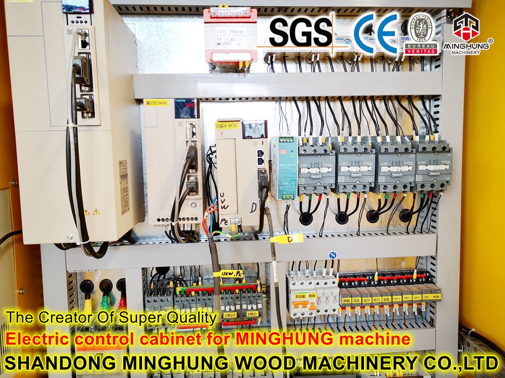
The general steps of PLC control system design can be divided into the following steps: Familiar with the control object and calculate the input/output equipment, PLC selection and hardware configuration, design electrical schematic diagram, design console (cabinet), compile control program, program debugging and prepare technical documentation.
1. Clarify the control requirements and understand the production process of the controlled object
Familiarity with the control object design process layout diagram is the basis of system design. First, you should understand the process of the controlled object and its requirements for the control system in detail, and the relationship between various mechanical, hydraulic, pneumatic, instrumentation, and electrical systems. The working mode of the system (such as automatic, semi-automatic, manual, etc.), the relationship between PLC and other intelligent devices in the system, the type of man-machine interface, the way of communication network, the type and scope of alarm, power failure and emergency treatment, etc. Wait.
At this stage, user input devices (buttons, operation switches, limit switches, sensors, etc.), output devices (relays, contactors, signal indicators, etc.) and control objects driven by output devices (motors, solenoid valve, etc.).
At the same time, it should also determine which signals need to be input to the PLC, which loads are driven by the PLC, and classify and count the nature and quantity of each input and output, whether it is digital or analog, DC or AC, and voltage. Size grades provide a basis for PLC selection and hardware configuration.
Finally, classify the control objects and control functions, which can be divided according to the signal use or control area, determine the physical location of the detection equipment and control equipment, and analyze the form, function, scale, and relationship between each detection signal and control signal Relationship. After the signal point is determined, the process layout or signal diagram is designed.
2. Hardware design of PLC control system
With the promotion and popularization of PLC, the types and quantities of PLC products are increasing. In recent years, there have been dozens of series and hundreds of models of PLC products imported from abroad, domestic manufacturers or self-developed products. There are many varieties of PLCs, with different structures, performances, capacities, command systems, programming methods, prices, etc., and different use occasions. Therefore, reasonable selection of PLC plays an important role in improving the technical and economic indicators of PLC control system.
1. Selection of PLC model
The choice of PLC model should be on the premise of meeting the control requirements, ensuring reliability, easy maintenance and use, and the best performance-price ratio. Specifically, the following aspects should be considered:
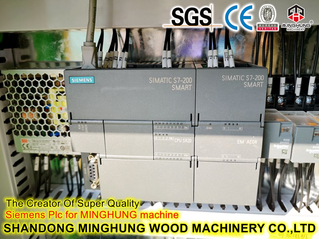
(1) The performance is compatible with the task. For small single-unit equipment that only needs digital control, general small PLCs (such as S7-200 series of Siemens, CPM1/CPM2 series of OMRON, FX series of Mitsubishi, etc.) Can meet the requirements.
For the application system mainly based on digital quantity control and with a small amount of analog quantity control, such as the control of continuous quantities such as temperature, pressure, and flow often encountered in industrial production, an analog quantity input module with A/D conversion and a The analog output module of D/A conversion is connected with the corresponding sensor, transmitter (the temperature module directly input by the temperature sensor can be selected for the temperature control system) and the driving device, and a small PLC with strong operation and data processing functions is selected. (Siemens' S7-200 or S7-300 series, OMRON's CQM1/CQM1H series, etc.).
For engineering projects with more complex control and higher control function requirements, such as PID calculation, closed-loop control, communication networking and other functions, the mid-range or high-end machine (such as Siemens S7-300) can be selected depending on the control scale and complexity. Or S7-400 series, C200H @ or CV/CVM1 series of OMRON company, Control Logix series of A-B company, etc.).
(2) The structure is reasonable, the installation should be convenient, and the model should be unified. According to the physical structure, PLC is divided into integral type and modular type. The average price of each I/O point of the integral type is cheaper than that of the modular type, so people generally tend to use the integral PLC in small control systems. However, the function expansion of modular PLC is convenient and flexible. The number of I/O points, the ratio of input points to output points, the type and number of I/O modules, and the use of special I/O modules are all more options than the overall PLC. The type PLC is much larger, and it is also very convenient to replace the module and judge the fault range during maintenance. Therefore, for more complex and demanding systems, modular PLC should generally be selected.
According to the distance and distribution range between the I/O equipment and the PLC, determine whether the PLC installation method is centralized, remote I/O or distributed with multiple PLCs.
For an enterprise, the design of the control system should try to achieve a unified model. Because the PLC of the same model, its modules can be used as backups for each other, which is convenient for the procurement and management of spare parts; its functions and programming methods are unified, which is conducive to the integration of technical forces. Training, improvement of technical level and development of functions; its external equipment is common and resources can be shared. Another advantage of the same type of PLC is that it is more convenient to compile communication programs when using a host computer to manage and control the PLC. In this way, it is easy to connect multiple independent PLCs into a multi-level distributed system, communicate with each other, and centralize management, giving full play to the advantages of network communication.
(3) Whether to meet the requirements of response time Since the modern PLC has a high enough speed to process a large amount of I/O data and solve the ladder logic, so for most applications, the response time of the PLC is not the main problem. However, for some individual occasions, it is required to consider the response time of PLC. In order to reduce the I/O response delay time of the PLC, you can choose a PLC with a high scanning speed, use high-speed I/O to process such functional instructions, or choose a fast response module and an interrupt input module.
(4) Requirements for networking communication functions In recent years, with the rapid development of factory automation, the enterprise is as small as the RS-485 serial communication of a temperature control instrument, as large as the communication of the Ethernet management layer of a manufacturing system, It should be said that general electrical control products have communication functions. PLC is the main control device of factory automation, and most products have communication networking capabilities. When choosing, you should choose the communication method according to your needs.
(5) Other special requirements Considering the special requirements of the controlled object for analog closed-loop control, high-speed counting, motion control and human-machine interface (HMI), PLC with corresponding special I/O modules can be selected. For systems with extremely high reliability requirements, it should be considered whether to use a redundant control system or a hot backup system.
2. PLC capacity estimation
The capacity of PLC refers to the meaning of two aspects, the number of I/O points and the storage capacity of user memory. When choosing a PLC model, you should not blindly pursue excessively high performance indicators, but in terms of I/O points and memory capacity, in addition to meeting the requirements of the control system, there should be a margin for backup or system expansion.
(1) Determination of I/O points
The determination of the number of I/O points of the PLC is based on the actual number of input and output points of the system. When determining the number of I/O points, an appropriate margin should be left. Usually, the number of I/O points can be considered as a margin according to 10~15% of the actual needs; when there are many I/O modules, a spare module is generally set aside according to the above ratio.
(2) Determination of memory capacity
How much storage capacity the user program occupies is related to many factors, such as I/O points, control requirements, calculation processing capacity, program structure, etc. Therefore, it can only be roughly estimated before programming.
3. Selection of I/O modules
In the PLC control system, in order to realize the control of the production process, various measurement parameters of the object should be sent to the PLC according to the required method. After calculation and processing by PLC, the result is output in the form of digital quantity. At this time, the output should be transformed into a quantity suitable for controlling the production process. Therefore, between the PLC and the production process, it is necessary to set up information transmission and conversion devices. This device is the input/output (I/O) module. Different signal forms require different types of I/O modules. For PLC, the signal form can be divided into four categories.
(1) Many status information of digital input signal production equipment or control systems, such as switches, buttons, relay contacts, etc., they have only two states: on or off, and the pick-up of such signals needs to be done through digital input modules to fulfill. The most common input module is 24V DC input, as well as DC 5V, 12V, 48V, AC 115V/220V, etc. According to the difference of the positive and negative potentials connected to the common terminal, it can be divided into sink type and source type. Some PLCs can be source-type wiring or sink-type wiring, such as S7-200. When the common terminal is connected to a negative potential, it is a source connection; when it is connected to a positive potential, it is a sink connection. Some PLCs can only be connected to one of them.
(2) The digital output signal also has many control objects, such as the on and off of the indicator light, the start and stop of the motor, the on and off of the thyristor, the opening and closing of the valve, etc., and their control only needs to be controlled by binary logic. "1" and "0" to achieve. This signal is driven by a digital output module. The digital output module is divided into relay output type, transistor output type, thyristor output type, etc. according to different output methods. In addition, the output voltage value and output current value are also different.
(3) Analog input signal Many parameters in the production process, such as temperature, pressure, liquid level, and flow rate, can be converted into corresponding analog signals through different detection devices, and then converted into digital signals and input to PLC. To accomplish this task is the analog input module.
(4) Analog output signals Many actuators of production equipment or processes are often required to be controlled by analog signals, while the control signals output by PLC are digital quantities, which requires corresponding modules to convert them into analog quantities. This module is an analog output module.
Typical analog modules range from -10V to +10V, 0 to +10V, 4 to 20mA, etc., which can be selected according to actual needs, and factors such as resolution and conversion accuracy should also be considered. Some PLC manufacturers also provide special analog input modules, which can be used to directly receive low-level signals (such as thermal resistance RTD, thermocouple, etc.)
In addition, some sensors such as rotary encoders output a series of pulses, and the output frequency is relatively high (above 20kHz). Although these pulse signals can also be counted as digital quantities, ordinary digital input modules cannot detect them correctly. Select a high-speed counting module.
Different I/O modules have different circuits and performances, which directly affect the application range and price of PLC, and should be selected reasonably according to the actual situation.
4. Assign input/output points
After the PLC model and input/output (I/O) modules are selected, first, design the overall configuration diagram of the PLC system. Then, according to the process layout diagram, refer to the specific PLC related instructions or manuals to connect the input signal with the input point and output control Draw the I/O wiring diagram corresponding to the signal and the output point one by one, that is, the PLC input/output electrical schematic diagram.
After the PLC model is selected, the number of input/output points is an important factor that determines the price of the control system and the rationality of the design. Therefore, in the case of completing the same control function, the number of input/output points can be simplified through reasonable design.
5. Safety circuit design
The safety circuit is a circuit that protects the load or the control object and prevents operation errors or control failures for chain control. While directly controlling the load, the safety protection circuit returns an input signal to the PLC, so that the PLC can perform protection processing. The safety loop generally considers the following aspects.
(1) Short-circuit protection A fuse should be installed in the external output circuit of the PLC for short-circuit protection. It is best to install fuses in the circuit of each load.
(2) Interlock and interlock measures In addition to ensuring the interlock relationship of the circuit in the program, hardware interlock measures should also be taken in the external wiring of the PLC to ensure the safe and reliable operation of the system.
(3) Loss of voltage protection and emergency stop measures The power supply line of the PLC external load should have a voltage loss protection measure. When the power supply is restored after a temporary power failure, the external load of the PLC cannot start by itself without pressing the "Start" button. Another function of this wiring method is that when an emergency stop is required under special circumstances, the load power can be cut off by pressing the "emergency stop" button, and the "emergency stop" signal is input to the PLC.
(4) Limit protection In some cases, such as hoists, which may cause danger if they exceed the limit, set limit protection. When the limit protection operates, the load power supply is directly cut off, and the signal is input to the PLC at the same time.
3. Software design of PLC control system
Software design is the core of PLC control system design. To design PLC application software well, we must fully understand the production process, technical characteristics, and control requirements of the controlled object. The various control functions of the system are completed through the application software of PLC.
1. Contents of PLC application software design
PLC application software design refers to the process of compiling user control programs and forming corresponding files according to the hardware structure and process requirements of the control system, using the corresponding programming language. The main contents include: determining the program structure; defining input/output, intermediate signs Parameter tables such as timers, counters and data areas; programming; writing program instructions. PLC application software design also includes the configuration of human-machine interface (HMI) devices such as text displays or touch screens and other special function modules.
2. Familiar with the controlled object to formulate equipment operation plan
On the basis of the system hardware design, according to the requirements of the production process, analyze the logical relationship between each input/output and various operations, and determine the detection amount and control method. And design the operation content and operation sequence of each equipment in the system. For more complex systems, the system can be partitioned and controlled according to physical location or control function. More complex systems generally need to draw a system control flow chart to clearly indicate the sequence and conditions of actions, and simple systems generally do not.
3. Familiar with programming language and programming software
Familiarity with programming language and programming software is the prerequisite for programming. The main task of this step is to have a detailed understanding of the programming software and its operating system used according to the relevant manuals, choose one or several suitable programming language forms, and be familiar with its instruction system and parameter classification, especially pay attention to those that may be used in programming. The commands and functions to use.
The best way to get familiar with the programming language is to operate on the computer, compile some test programs, and conduct trial runs on the simulation platform, so as to understand the functions and uses of the instructions in detail, lay a good foundation for subsequent program design, and avoid detours.
4. Define the parameter table
The definition of the parameter table includes the definition of input/output, intermediate flag, timer, counter and data area. The definition format and content of the parameter table are different according to the system and personal preference, but the content contained is basically the same. The general design principle is ease of use and as much detail as possible.
The input/output signal table must first be defined before programming begins. The main basis is the PLC input/output electrical schematic diagram. The input point number and output point number of each PLC has its own clear regulations. After the PLC model and configuration are determined, the input/output signal of the PLC must be allocated to the input/output number (address) and compiled into a table.
In general, the input/output signal table should clearly mark the position of the template, input/output address number, signal name and signal type, etc. In particular, the input/output definition table annotation content should be as detailed as possible. The addresses should be arranged in order from small to large as far as possible, and don’t miss the undefined or spare points, so that it is easy to find and use when programming, debugging and modifying the program.
However, the intermediate flags, timers, counters and data areas may not be well defined before programming. Generally, they are defined as they are used during the programming process, and they are unified with the input/output signal table in the middle of the programming process or after the programming is completed.
5. Programming
If there is operating system support, try to use the advanced form of programming language, such as ladder diagram language. During the writing process, according to the actual needs, define the intermediate flag signal table and the storage unit table one by one, and pay attention to reserve enough public temporary storage areas to save memory usage.
Since many small PLCs use simple programmers, only instruction codes can be input. After the ladder diagram is designed, it is also necessary to compile the code program of the ladder diagram according to the instruction statement, and list the program list. After being familiar with the selected PLC command system, it is easy to write a statement list program according to the ladder diagram.
In the process of writing the program, it is necessary to comment on the compiled program in time to avoid forgetting the relationship between them. The comment should include the description of the program segment function, logical relationship, design idea, source and destination of the signal, etc., so as to facilitate the reading and debugging of the program .
6. Program testing
Program testing is an important part of the whole program design work, it can preliminarily check the actual running effect of the program. Program testing and program writing are inseparable, and many functions of the program are modified and perfected in the test.
When testing, start with each functional unit, set the input signal, observe the effect of the change of the input signal on the system, and use instruments and meters if necessary. After the test of each functional unit is completed, connect all programs and test the interface of each part. until satisfied.
Procedural testing can be done in a laboratory or on-site. If the program test is carried out on site, it is necessary to isolate the PLC from the site signal to avoid accidents.
7. Compilation of program manual
The program manual is a comprehensive description document of the entire program content and a summary of the entire program design work. The main purpose of writing is to let the users of the program understand the basic structure of the program and how to deal with certain problems, as well as the method of reading the program and the matters that should be paid attention to during use.
The program specification generally includes the basis of the program design, the basic structure of the program, the analysis of each functional unit, the formulas and principles used, the source and operation process of each parameter, the test situation of the program, etc.
Each step in the above process is an indispensable link in the application program design. To design a good application program, each link must be done well. However, the core of application programming is the writing of the program, and other steps are in its service.
8. Commonly used programming methods
PLC programming methods mainly include experience design method and logic design method. The logic design is based on the logic algebra, by writing the logic expressions of the input and output, and then converting it into a ladder diagram. Because the general logic design process is more complicated and the cycle is longer, most of them adopt the empirical design method. If the control system is more complicated, you can use the flow chart. The so-called empirical design is based on some typical applications, according to the specific requirements of the controlled object for the control system, select some basic links, properly combine, modify, and improve, so that it becomes a program that meets the control requirements. The general empirical design method has no common The rules can be followed, and only by continuously accumulating and enriching oneself in a large number of program designs, and gradually forming one's own design style. The quality of a program design and the time it takes often have a lot to do with the experience of the programmer.
Many of the so-called commonly used basic links are derived from the conversion of the relay contactor control circuit. It is very similar to the circuit diagram of the relay contactor, and the signal input, output and control functions are also roughly the same. For engineers and technicians who are familiar with the design principles of relay contactor control systems, it is undoubtedly very convenient and fast to master the design of ladder diagram language.
4. Anti-interference design of PLC control system
Although PLC is specially designed for industrial production environment and has strong anti-interference ability, if the environment is too harsh, the electromagnetic interference is particularly strong or the PLC is installed and used improperly, it may still affect the safety and reliability of the PLC control system. Bring hidden dangers. Therefore, in the design of PLC control system, it is also necessary to pay attention to the anti-interference design of the system.
1. Measures against power interference
Practice has proved that there are many situations where the PLC control system fails due to the interference introduced by the power supply. The normal power supply of the PLC system is powered by the grid. Due to the wide coverage of the power grid, it will be subject to electromagnetic interference in all spaces and induce voltage and current on the line. Especially changes within the power grid, switching operation surges, start and stop of large power equipment, harmonics caused by AC and DC transmissions, and power grid short circuits Transient impact, etc., are transmitted to the power supply through the transmission line. Take the following measures to reduce the failure of the PLC control system caused by power supply interference.
(1) Use a power supply with excellent performance to suppress the interference introduced by the power grid. In the PLC control system, the power supply occupies a very important position. Power grid interference into the PLC control system is mainly through the power supply of the PLC system (such as CPU power supply, I/O power supply, etc.), the transmitter power supply and the instrument power supply with direct electrical connection with the PLC system. Now, For the power supply of the PLC system, the power supply with better isolation performance is generally used, but for the power supply of the transmitter and the power supply of the instrument with direct electrical connection to the PLC system, it has not received enough attention, although a certain amount of isolation has been adopted. Measures, but generally not enough, mainly because the distribution parameters of the isolation transformer used are large, the ability to suppress interference is poor, and common-mode interference and differential-mode interference are connected in series through power coupling. Therefore, for the power supply of transmitters and shared signal instruments, distributors with small distributed capacitance and large suppression bands (such as multiple isolation and shielding and leakage inductance technologies) should be selected to reduce the interference of the PLC system. In addition, in order to ensure uninterrupted grid feed, uninterruptible power supply (UPS) can be used to improve the safety and reliability of power supply. And UPS also has strong interference isolation performance, which is an ideal power supply for PLC control system.
(2). Hardware filtering measures In the occasions with strong interference or high reliability requirements, an isolation transformer with shielding layer should be used to supply power to the PLC system. A filter can also be connected in series on the primary side of the isolation transformer, as shown in the figure.
(3) Correctly select the grounding point and improve the grounding system
2. Grounding design of the control system
Good grounding is an important condition to ensure the reliable operation of PLC, which can avoid accidental voltage shock hazards. There are usually two purposes of grounding, one is for safety, and the other is to suppress interference. A perfect grounding system is one of the important measures for the PLC control system to resist electromagnetic interference. The grounding methods of the grounding system can generally be divided into three methods: series single-point grounding, parallel single-point grounding, multi-branch single-point grounding, which is the third A grounding method. PLC adopts the third grounding method, that is, separate grounding.
The ground wire of the PLC control system includes system ground, shielding ground, AC ground and protection ground. The disturbance of the grounding system to the PLC system is mainly due to the uneven distribution of the potential of each grounding point. There is a ground potential difference between different grounding points, which causes a ground loop current and affects the normal operation of the system. For example, the cable shielding layer must be grounded at one point. If the cable shielding layer If both ends are grounded, there is a ground potential difference, and current flows through the shielding layer. When abnormal conditions such as lightning strikes occur, the grounding current will be greater. In addition, the shielding layer, grounding wire and the ground may form a closed loop. Under the action of the changing magnetic field, an induced current will appear in the shielding layer, which will interfere with the signal circuit through the coupling between the shielding layer and the core wire. If the system is confused with other grounding, the resulting ground circulation may produce unequal potential distribution on the ground, which will affect the normal operation of the logic circuit and analog circuit in the PLC. The logic voltage interference tolerance of the PLC is low, and the logic The distribution interference of the ground potential can easily affect the logical operation and data storage of the PLC, resulting in data confusion, program runaway or crash. The distribution of the simulated ground potential will lead to a decrease in measurement accuracy, causing severe distortion and misoperation of signal measurement and control.
3. Measures to prevent I/O interference
The interference introduced by the signal will cause the I/O signal to work abnormally and the measurement accuracy will be greatly reduced. In severe cases, it will cause damage to components. For systems with poor isolation performance, it will also cause mutual interference between signals, cause common ground system bus backflow, and cause logic data changes, malfunctions or crashes. The following measures can be taken to reduce the impact of I/O interference on the PLC system.
(1) Select I/O modules from the perspective of anti-interference
(2) Attention during installation and wiring:
①The power lines, control lines, and PLC power lines and I/O lines should be wired separately, and the isolation transformer should be connected with the PLC and I/O with twisted pairs. Separate the I/O line and the high-power line of the PLC. If they must be in the same line slot, a partition can be added. It is best to route the lines in separate slots. Keep distractions to a minimum.
②PLC should be far away from strong interference sources such as electric welding machines, high-power silicon rectifiers and large power equipment, and cannot be installed in the same switch cabinet as high-voltage electrical appliances. The PLC in the cabinet should be far away from the power line (the distance between the two should be greater than 200mm). Inductive loads installed in the same cabinet as the PLC, such as relays with high power and coils of contactors, should be connected in parallel with RC circuits.
③The input and output of the PLC should be routed separately, and the switching value and analog value should also be laid separately. The transmission of analog signal should use shielded wire, the shielding layer should be grounded at one end, and the grounding resistance should be less than 1/10 of the resistance of the shielding layer.
④ Do not use the same cable for the AC output line and the DC output line, and the output line should be as far away from the high-voltage line and power line as possible to avoid parallel.
(3) Consider the wiring of the I/O terminal:
Generally, the input wiring should not be too long, but if the environmental interference is small and the voltage drop is small, the input wiring can be appropriately longer. The input/output lines should be separated. Connect to the input terminal in the form of a normally open contact as much as possible, so that the compiled ladder diagram is consistent with the relay schematic diagram, which is easy to read. Except for emergency stop, limit protection, etc.
The output terminal wiring is divided into independent output and common output. In different groups, output voltages of different types and voltage levels can be used. But the output in the same group can only use the power supply of the same type and the same voltage level. Since the output components of the PLC are packaged on the printed circuit board and connected to the terminal board, if the load connected to the output components is short-circuited, the printed circuit board will be burned. When the relay output is used, the size of the inductive load it bears will affect the service life of the relay. Therefore, when using an inductive load, it should be selected reasonably, or an isolation relay should be added.
(4) Choose the grounding point correctly and improve the grounding system
(5) Suppression of frequency converter interference
5. Debugging of PLC control system
System debugging is a necessary step before the system is officially put into use. Different from the relay control system, the PLC control system has both hardware debugging and software debugging. Compared with the relay control system, the hardware debugging of the PLC control system is relatively simple, mainly the compilation and debugging of the PLC program. Generally, it can be carried out according to the following steps: application program compilation and offline debugging, control system hardware inspection, application program online debugging, on-site debugging, summarizing relevant materials, and the system is officially put into use.

