1. Main Frame & Bed
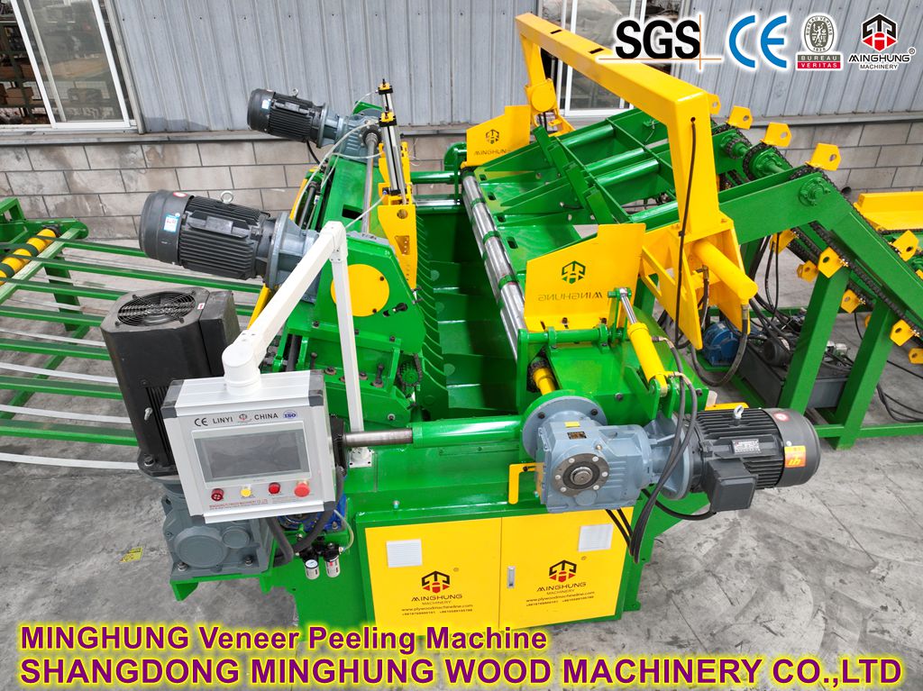
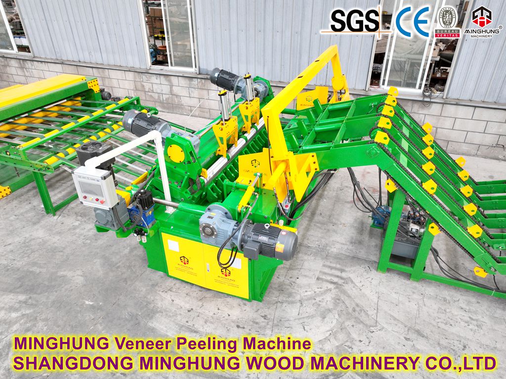
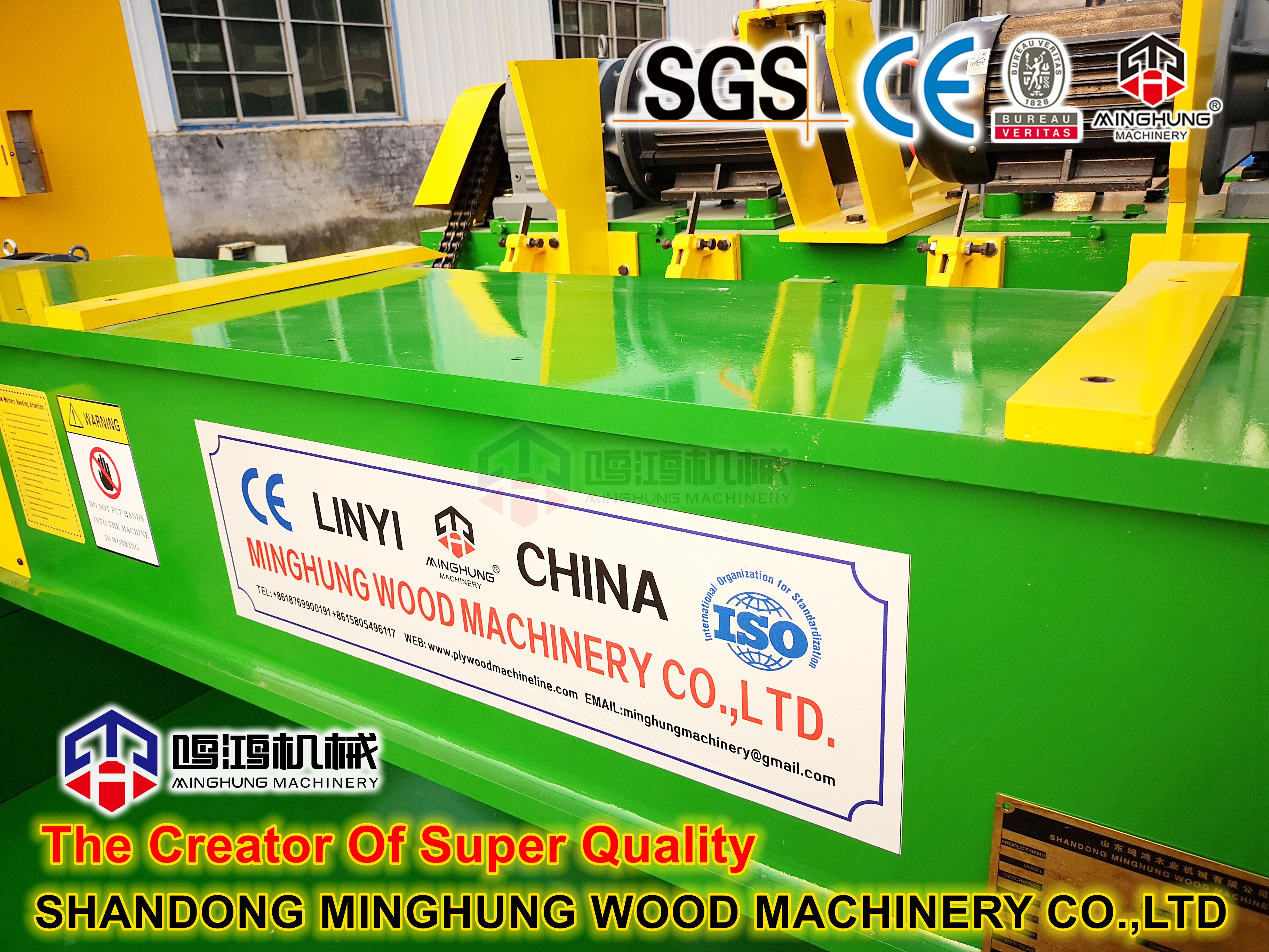
This forms the foundation and skeleton of the entire machine. It is a heavy-duty, welded box-type structure made from thick steel plates, stress-relieved and precision-machined. Its exceptional rigidity and stability are fundamental for withstanding immense peeling torque, ensuring cutting accuracy, and guaranteeing long equipment life.
2. Spindless Drive & Clamping System
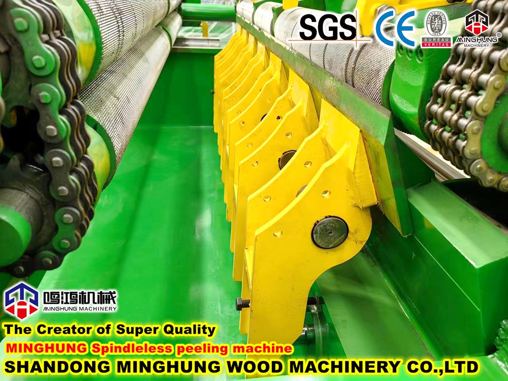
Bottom Main Drive Roller: The core driving component. Typically a large steel roller covered with a special high-friction, wear-resistant rubber or polyurethane layer. It is directly driven by a high-torque, large-displacement low-speed hydraulic motor, providing the primary power for log rotation.
Top Pressure Roller: Positioned directly above the drive roller, its vertical movement is controlled by heavy-duty hydraulic cylinders. During operation, it applies significant downward force, working in tandem with the drive roller to clamp the log securely and drive its rotation via friction. The pressure is adjustable based on log diameter and species.
Lateral Auxiliary Support/Centering Rolls (Optional on some models): Hydraulic or pneumatic support rolls located on both sides of the log. They help stabilize logs with a low length-to-diameter ratio, preventing lateral rolling or shifting during peeling, serving as an auxiliary centering function.
3. Hydraulic Power System
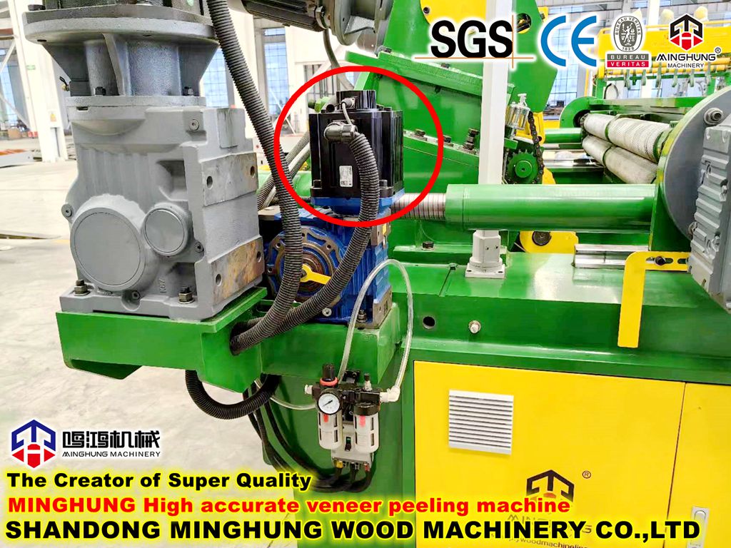
Hydraulic Power Unit: Includes a high-power main motor, high-pressure variable displacement piston pump, oil tank, cooler, filtration system, and valve blocks. Acting as the "heart" of the machine, it provides a stable, adjustable high-pressure oil supply for all hydraulic actions.
Hydraulic Control Valve Bank: Integrates proportional valves, servo valves, or cartridge valves to precisely control the speed and direction of the drive roller, the movement and pressure of the pressure roller, and the speed/pressure of the tool rest feed cylinder, enabling smooth and precise motion control.
4. Cutting System
Heavy-Duty Tool Rest Assembly: Comprises a robust tool rest body, a knife holder for mounting and adjusting the peeling knife, and a Pressure Bar device. The pressure bar pre-bends wood fibers ahead of the cutting edge, effectively reducing checks on the backside of the veneer, which is crucial for producing thick, sturdy formwork veneer.
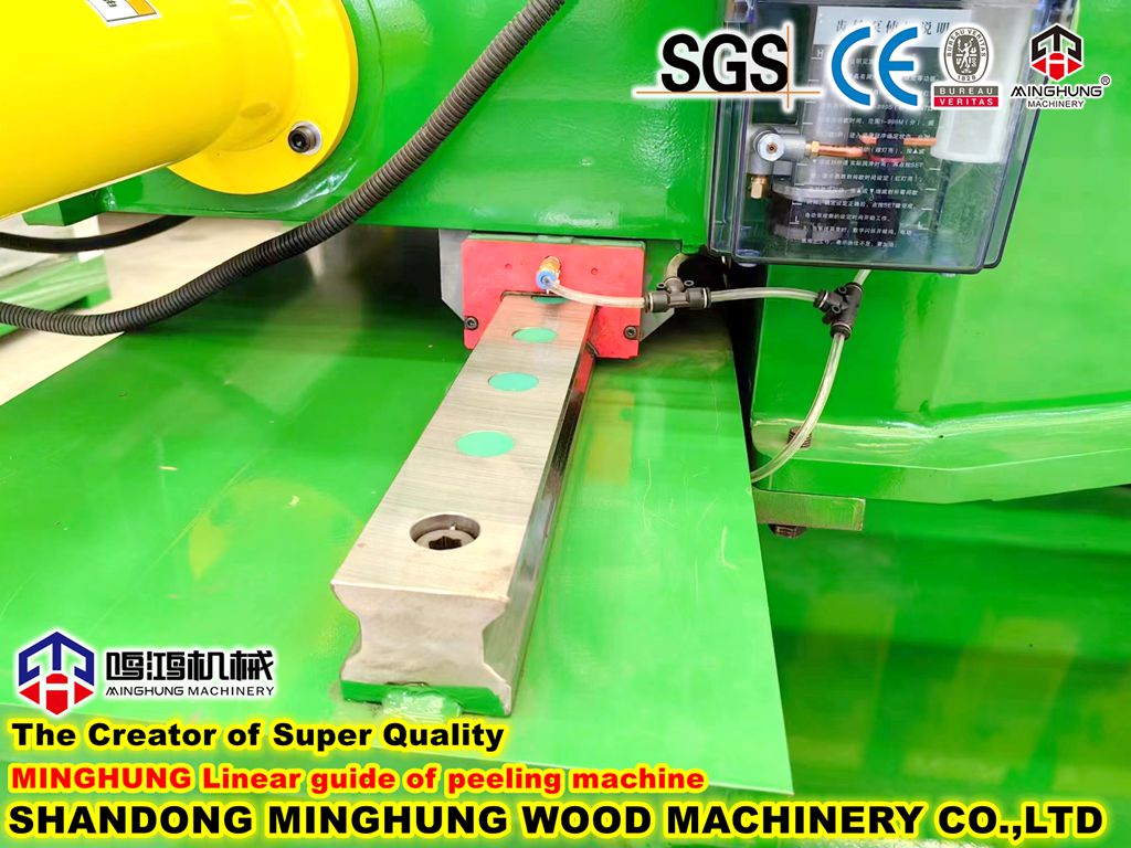
Tool Rest Feed Mechanism: Typically, a large-diameter hydraulic cylinder drives the tool rest along heavy-duty linear guides for precise feed motion. The feed speed is accurately controlled by a hydraulic proportional system to ensure uniform veneer thickness. Some high-end models employ "servo-hydraulic" or "motor-ball screw" systems for feed control to achieve higher precision.
5. Veneer Conveying & Handling System
Rear Conveying Unit: Located behind the knife opening, it consists of a series of synchronously driven rollers or a wide conveyor belt. Its function is to receive and smoothly draw out the continuous ribbon of peeled veneer from the machine, preventing jams or tears.
Clipper Interfacing: The machine's tail section is designed with mechanical or electronic interfaces for seamless connection to a subsequent veneer clipper, enabling continuous production from peeling to length-cutting.
6. Electrical Control System
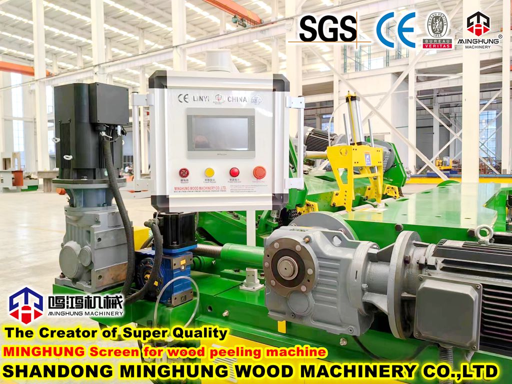
Main Control Cabinet: Houses the PLC (Programmable Logic Controller), power modules, relays, drivers, and other electrical components. The PLC is the core for logical control, sequence of operations, and parameter calculations.
Human-Machine Interface (HMI): An industrial touchscreen providing an intuitive interface for setting parameters (veneer thickness, log diameter, pressure), monitoring machine status, viewing alarms, and production data.
Sensors & Detection Elements: Include position sensors (for tool rest, pressure roller), pressure transducers, rotary encoders, etc., providing real-time feedback to the control system for closed-loop control.
7. Auxiliary & Safety Systems
Centralized Lubrication System: Automatically injects grease at timed intervals to critical friction points like guide rails and bearing housings, reducing wear and maintaining long-term operational accuracy.
Safety Guards & Devices: Include full or mesh guards covering rotating and moving parts, emergency stop buttons, safety light curtains, or interlocked doors to ensure operator safety.
Core/Waste Ejection System: A chute or conveyor at the machine's bottom for automatically discharging the remaining small-diameter peeler core or waste material after peeling.